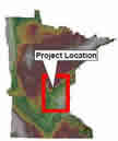
Landform Sediment Assemblages in the Anoka Sand Plain for Support of Cultural Resource Investigations

Location of Anoka Sand Plain
Prepared
for:
Minnesota Department of Transportation
Prepared
by:
Edwin R. Hajic, Curtis M. Hudak, and Jeffrey Walsh
Foth Infrastructure and Environment, LLC
June 2009
- Report Text
- Report Tables
- Appendix A: Map Unit Field Code Key Table
- Appendix B: Anoka Sand Plain Core Descriptions
- Appendix C: Radiocarbon Laboratory Reports
Figures (PDF)
- Figure 1: Anoka Sand Plain Project Area and Affiliated Core Locations
- Figure 2: Area 1 Core Locations and Cross-Section Line
- Figure 3: Area 1 Stratigraphy and Graphic Sediment Soil Logs
- Figure 4: Area 2 Core Locations and Cross-Section Line
- Figure 5: Area 2 Stratigraphy and Graphic Sediment Soil Logs
- Figure 6: Area 3 Core Locations and Cross-Section Lines
- Figure 7: Area 3 Stratigraphy and Graphic Sediment Soil Logs
- Figure 8: Area 4 Core Locations and Cross-Section Line
- Figure 9: Area 4 Stratigraphy and Graphic Sediment Soil Logs
- Figure 10: Area 5 Core Locations and Cross-Section Line
- Figure 11: Area 5 Stratigraphy and Graphic Sediment Soil Logs
- Figure 12: Area 6 Core Locations and Cross-Section Lines
- Figure 13: Area 6 Stratigraphy and Graphic Sediment Soil Logs
- Figure 14: Areas 7, 8, 9, and 10 Core Locations
- Figure 15: Areas 7, 8, 9, 10 Stratigraphy and Graphic Sediment Soil Logs
- Figure 16: Training Area for Remote Sensing Data
- Figure 17: LANDSAT Classification Results for Buried Soils Detection
- Figure 18: Stratigraphic Summary of Major Landscapes on the Anoka Sand Plain
